The wedge tool: drawing circular quadrants, rings, and related geometries in QGIS
Fellow researchers and open-source GIS enthusiasts,
Welcome to my blog!
I’d like to start with a disclaimer – I may be a researcher of this very area but that doesn’t mean everything I do or write here will work for you, in your own desktop configurations and package versions. I have no responsibility if you lose data or mess up your installation. I also do not authorize any copies of my content, except for the gists, which are available under the MIT License.
Today, I am talking about all things wedges in QGIS. This tool is very useful to generate complex geometries which involve circles, rings, or circular sectors. I am using QGIS 3.20 Odense for the examples shown.
Generating such geometries can be useful for many applications, notably zoning and sampling. As an example, it can be used to map an exclusion zone (hot zone) and a contamination reduction zone (warm zone) around a toxic leakage, in a much quicker and easier way than using Buffer and Difference tools. It can also be used to classify the locations in a town, relative to its center, in order to develop different development plans for each of them. Among its many uses, another one is to classify the location (e.g. N, NW, SE) of a given sample, in relation to the centroid of the polygon in which the samples are contained (example, a river basin), in order to check if the samples acquired in the field are well-distributed enough. Wedge is is not one of the most popular tools of QGIS, although it is, in fact, very versatile.
After the examples provided in this post, I also provide a Python code to be run in the Python Console of QGIS (PyQGIS) which does the same as I did in the User Interface dialog. Here in my examples, I’m saving the outputs in temporary scratch files, saved in the temporary folder of QGIS. I recommend you briefly read my previous post about temporary scratch layers before diving into the the wedge tool of QGIS.
The wedge tool in QGIS User Interface
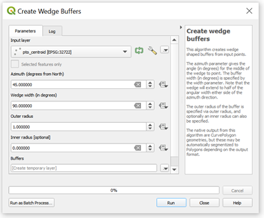
Type “wedge” in the Processing Toolbox and the tool “Create wedge buffers” should be shown.
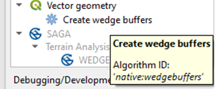
When I click it, this dialog appears:
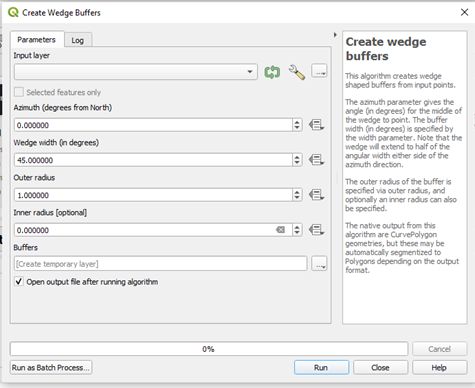
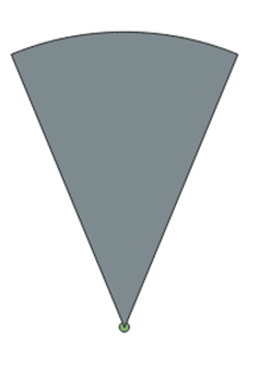
The input layer should be a point layer, in which there should be a point. The coordinates of this point should be the center of the circle (or wedge, or semi-circle). The default width of the wedge is 45°, or one-eight of a circle and the default azimuth of the wedge is 0°. The outer radius is what we are used to simply call a radius of a circle, and the inner radius variable will only be filled when we want to draw a ring or donut-like geometry. I suggest you pay attention to the projection being used when you fill the values for the inner and outer radius.
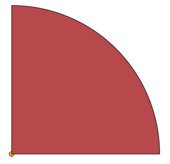
If I leave the original settings and add a point layer for which to generate the wedge, this should be the result:
On PyQGIS
To do the same operation on PyQGIS, first, open the Python Console of QGIS.
Set the parameters to run the wedge algorithm:
paramwedge={ 'AZIMUTH' : 0, 'INNER_RADIUS' : 0, 'INPUT' : 'point.shp', 'OUTER_RADIUS' : 1, 'OUTPUT' : 'memory:' , 'WIDTH' : 45}
And run it:
layer_wedge=processing.run("native:wedgebuffers", paramwedge)
QgsProject.instance().addMapLayer(layer_wedge['OUTPUT'])
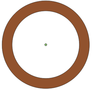
Drawing a ring or donut geometry
To draw a donut-like shape in QGIS, you should fill the wedge width as 360° (a full rotation). The most important part of the settings is filling the inner radius value with a value different from zero. With an inner radius of 1.0 and outer radius of 1.3, the resulting ring is:
Drawing quadrants
By definition, quadrants divide the circle into 4 parts. The width of each part should be 0.25 of the width of a whole circle (360°). Therefore, 90°.
The next step is to define the azimuth of each quadrant in order to draw them in QGIS using the wedge tool.
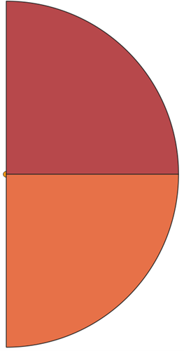
The right top quadrant starts in an angle of 0 degrees and ends in an angle of 90 degrees. That means its azimuth must be 45 degrees, which is halfway between 0 and 90.
After clicking “Run”, I obtained:
This is the first quadrant drawn. Now, how to draw the remaining ones?
We should think of it as a clockwise progression. If the first quadrant ended in 90°, then this is where the next one should start. It should, therefore, end in 180°, and be centered in (90+180)/2= 135. Therefore, the azimuth of the next one is 135°, while the width is, of course, still 90°.
Now, the two remaining quadrants are centered in (180+270)/2=225 and (270+360)/2=315.
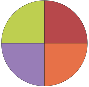
Done!
Dividing the circle into a different number of equal width sectors
To generate wedges of equal widths, first, determine the width (in degrees) of each one of the wedges. The angular width should be 360/(number of sectors).
The azimuth should progress from $width/2$ to $360-(width/2)$. The azimuth values can be represented by the expression $width/2 + width*k$, in which $k=0,1,…,n$
If you don’t feel like using the UI, I coded a snippet that generates these wedges automatically, to be ran on PyQGIS (Python Console of QGIS):
In this code, the only variable you need to fill is the number of sectors (numsectors).
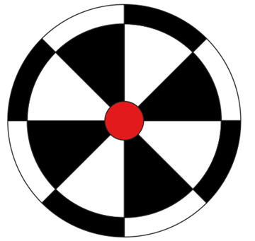
Target-like geometry on QGIS
To draw the inner part of the target, use the code in the previous gist. I suggest using 8 equal sectors.
To draw the outer part of the target, set the inner radius of the ring as the (outer) radius of the inner part.
To draw the bullseye, use the wedge tool with an inner radius of zero, and a small outer radius.
The resulting geometry is:
Now, adjust the symbology accordingly. Example:
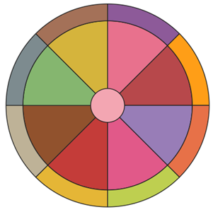
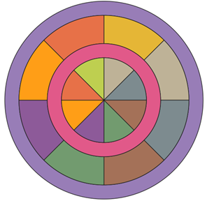
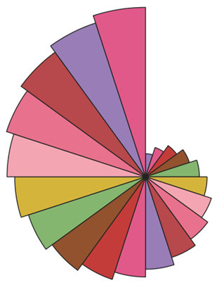
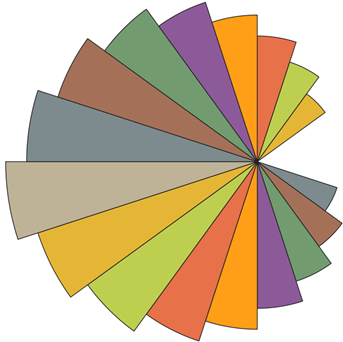
I’ll leave some more examples of the multiple uses of the wedge tool of QGIS below:
Extras
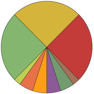
- How to draw the last example shown?
To draw this wedge composition, the radius of the generated wedge is altered at each step.
Provide the initial outer radius of the wedge and alter it inside the loop.
This is the gist that was used to generate the varying radius wedges:
Luísa Vieira Lucchese
Research Assistant Professor
Research Assistant Professor at University of Pittsburgh